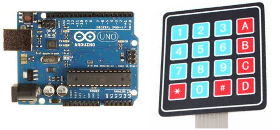
Serial 4 X 4 Keypad Schematic

In this post we will discuss logic and interface of a matrix keypad (4x4 for this post) with microcontroller to reduce the number of port pins required to read a certain number of inputs (digital). The same logic applies to any matrix keypad of order NxN. Where, N is the order of the matrix. Tupperware Fundraiser Order Form Template. Why Matrix Keypad? Typically one port pin is required to read a digital input into the controller.
4x4 is only 4 bits, post your schematic. With the solution I gave you could have either serial or parallel output. 16 BUTTON KEYPAD (4 X 4). Arduino - 4x5 Matrix Keypad Example Code and Schematic. 4x5 Matrix Keypad Example Code and Schematic. You can see what value is what key in the serial monitor. There are a lot of instructions and examples of how to connect a 4 x 3 membrane keypad but I couldn't find instructions on how to connect a 4 x 4 Membrane Keypad to. 1x4 Membrane Keypad W/ Arduino. * 1x4 Keypad w/ primary pin attached to Ground and 1-4 keys attached to PINS 9-12 * Serial Monitor used for output.
Gradius Gaiden Psx Rom. When there are a lot of digital inputs that have to be read, it is not feasible to allocate one pin for each of them. This is when a matrix keypad arrangement is used to reduce the pin count. Therefore, the number of pins that are required to interface a given number of inputs decreases with increase in the order of the matrix. From the circuit you can see that when one of the 16 buttons are pressed, a pair of pins are connected together.
We will use this feature to detect the button that was pressed in the following sections. Matrix Keypad Interface Logic Initially all switches are assumed to be released. So there is no connection between the rows and columns.
When any one of the switches are pressed, the corresponding row and column are connected (short circuited). This will drive that column pin (initially high) low. Using this logic, the button press can be detected. The colors red and black is for logic high and low respectively. Here are the steps involved in determining the key that was pressed. Driver Epson Lq 570 Xp Drivers there. Step 1: The first step involved in interfacing the matrix keypad is to write all logic 0’s to the rows and all logic 1’s to the columns. In the image, black line symbolizes logic 0 and red line symbolizes logic 1.
For now let us assume that, the circled key is pressed and see how the key press can be detected by a software routine. We already know that the key press happened at column 2. Now we have detected that the key is in row 2. So, the position of the key in the matrix is (2,2) Once this is detected, its up to us to name it or provide it with a task on the event of the key press.
Implementation with C Now lets see how the above logic can be implemented in embedded C. Here is the program I wrote to test it. This code is for PIC microcontrollers with c18 lite version compiler. I as usual, used a lot of macros so if you are an Arduino user you could easily make some alterations to the code and use it.
The basic concept for keypad scan is inside the while(1) loop.